I saw somebody's arduino based voltmeter clock way back around 2014, I think here: https://maniacallabs.com/2014/07/08/meter-clock-pt1/
I thought it was pretty cool, but a bit expensive for what it was.
So I made my own with a PIC chip: https://www.n1kdo.com/meter-clock/index.html
Mine is more of a novelty than a accurate clock. It is a interesting desktop geegaw to invite discussion.
> https://www.n1kdo.com/meter-clock/index.html
Can't access it. Connection attempts time out.
https://web.archive.org/web/20250410222119/https://www.n1kdo...
Your AS might be blocked by firewall rules. The Wayback Machine can show you the page.
Good luck with random AS blocks. Sounds thoughtful.
I always enjoy projects like this. Both because the are artistically neat and because the give me all sorts of ideas.
It's certainly nice to see the nice woodworking in combination with a simple elegant design.
Ways to keep more than one brain center active!
And it goes really well as a aesthetic choice too!
Funny, I've been playing with panel-meters as well…
I have an analog computer I'm finishing up. I have ADC's to convert the analog to digital to display the values on an LCD (with an ESP32 dev board—it was more flexible than panel meters, cheaper than an oscilloscope).
But because looking at "simulated" panel-meters seemed to kind of undercut the point of the analog computer, I went ahead and created a small PCB to go from my analog computer to a panel meter like the one in the clock.
Running a "Spring + Mass" simulation on the analog computer and seeing both the LCD/ESP32 representation of a panel meter and an actual panel meter move in sync brought it all home.
So sexy! I could probably build the electronics easily enough, but such projects need workworking tools I just don't have room for in my tiny flat.
(nor would the missus be pleased for me to buy them - but that's another matter)
If there's a makerspace or hackerspace near you, they might have a CNC router. Apart from (I believe) the front panel being a two-sided job, this is pretty straightforward and could be done entirely on a Shopbot or equivalent. Worst case you might need to learn FreeCAD and buy some collets ($10-$50) and bits (~$50-$75 if you're getting two). Best case, they have software and tooling you can use.
Source: am a furniture maker professionally. Have worked out of a makerspace, and have done equivalently complex projects on their Shopbot.
Edited to add: if you skip the rabbets around the gauges on the front panel, you can make that a single-sided CNC job, which makes it much easier. With some care, you could do those with a handheld router and a rabbetting bit.
You should check your local libraries too. Some have all kinds of crazy tools you can borrow or use on-site.
I built one of these recent after Princess Auto had an amazing deal on surplus meters like these. They were under just over 1$ each and I bought a lot of them.
The one I built isn't as nice, but it's a really nice way to display the time and people are mildly fascinated by it when they see it.
Nice! Needs just a tweak to prevent the overshoot and bounce when going from high to low.
Nah the bounce is gorgeous
Wut? We add extra lines of code just to get that in digital?
;-)
For that, you just need to not make the transition from 100% duty cycle to 0% duty cycle instantaneous, but to ramp down linearly the duty cycle over a large fraction of a second or even an entire second.
As another poster said, the overshoot may look cool, but I would be worried that a cheap panel voltmeter would not survive a very large number of such shocks.
A linear ramp would work, but you can probably get to the end-point quicker if you're not going linearly. Something like
needle_position = needle_position * 0.9 + desired_needle_position * 0.1
is very easy to implement, easier than linear if you ask me, and should give it a nice damped movement. The constants can be tuned to go as quick or as slow as you like of course.
You can do better: cut to 0%, let the needle fall, go back to 100% for a moment to catch the needle as it approaches the bottom of the scale. If you want to be fancy, add some quick sinusoidal ramps to smooth out the derivative.
making it worse with more code is not trend one should follow
Cool! I was at least hoping for an op amp or two for the circuit however ;)
Random idea:
volts as Hours amps as Minutes
Resulting wattage drives an iridescent bulb
I think I don't completely understand your idea. The current flowing through the amperemeter¹ depends on the voltage and the resistance of the incandescent(?) lamp. To vary current by the minute, you would need a digital resistor or potentiometer, I guess. Is that your suggestion?
¹) I just found out that it is more commonly called 'ammeter' in English - which is so unintuitive that I prefere 'amperemeter'.
If you have a feedback loop I'm sure you can still do it with an either implicitly or explicitly filtered PWM. Remember we're talking averages not instantaneous, so the average current through the bulb should be proportional to the average voltage across it, though the resistance will change as the bulb heats hence the feedback. You could also do this with a buck/boost regulator and current sense resistor plus op amps to create a constant current supply.
"average current through the bulb should be proportional to the average voltage across it" That is exactly correct, the reason they were seeking clarification, and the core of suggested solution.
V=I*R
If V = Hours and I = Minutes, then by necessity R=Hours/Minutes. Typically a light bulb has mostly fixed resistance (R). Adding a potentiometer to the circuit allows you control the value of R.
So lightbulbs actually dont have fixed resistance. The tempco is pretty big, and temperature of course depends on power (with an annoyingly large time lag when power is reduced).
That being said, the bulb does have a well-defined resistance at a given point in time, so voltage and current are of course not quantities that can be indefinitely controlled.
This falls into the same category as “why isn’t my power supply with voltage and current controls working correctly?!?”
Oh maybe I misunderstood. I thought they meant separate meters, so I didn't understand what was hard about that
Oh - it didn't occur to me that the original poster might have thought about three different circuits - one with a voltmeter, one with an amperemeter, and one driving the light bulb. Maybe that was their intention.
I originally assumed that the bulb would be somehow connected to voltmeter and amperemeter.
I suspect you meant "incandescent".
Iridescence essentially would mean it has a groovy, far-out metallic layer making rainbows on the surface. Not bad, but irrelevant.
PS: Neither of those would really communicate the needed information, except as an extreme (11:59 pm would look just like 10:27 pm, but very different from 12:01 am).
The build itself is absolutely wonderful! This part is totally my hangup, but a second hand that has to reset bugs me to no end. :/
I like this! Now I want to build one, too.
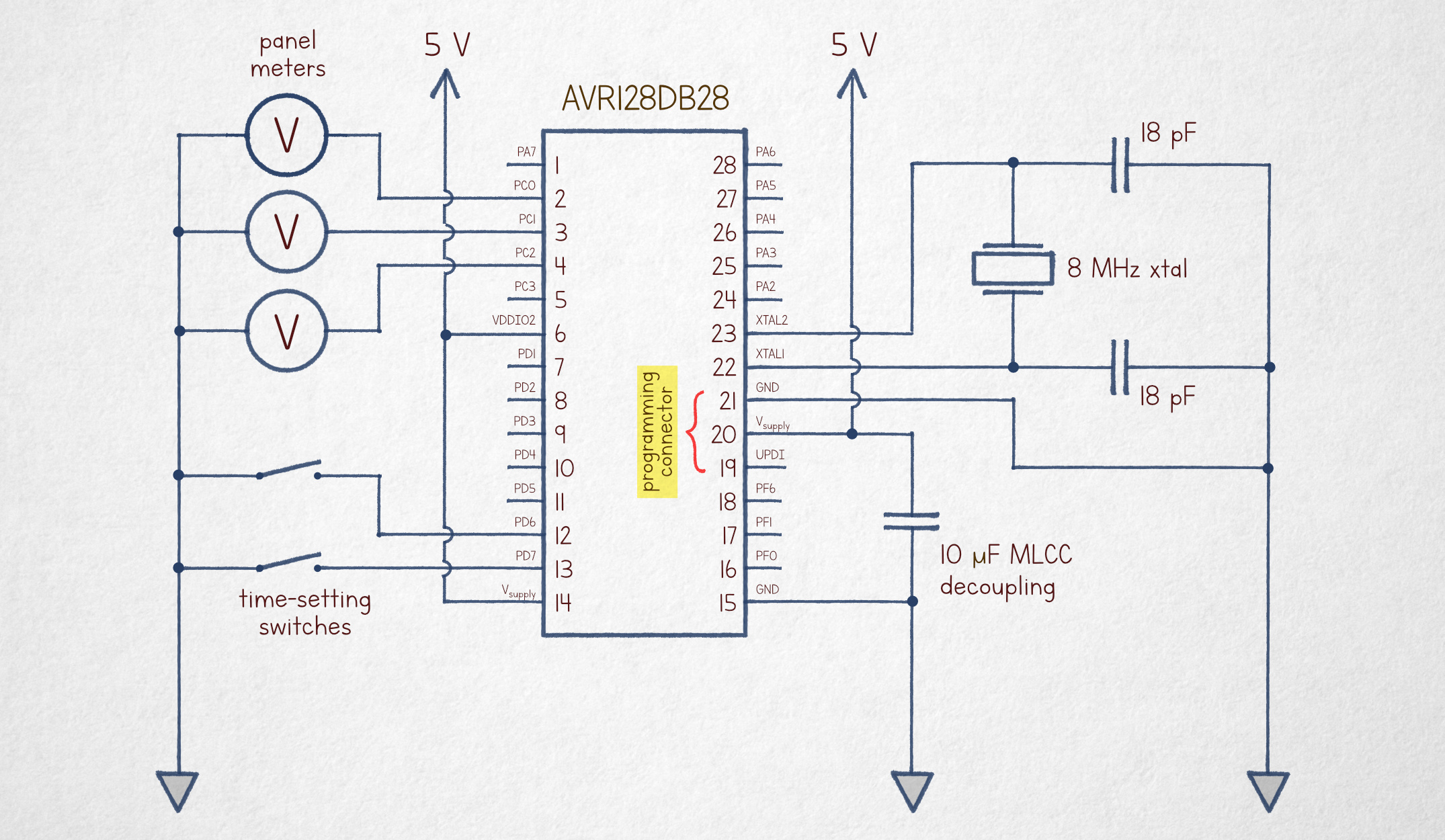
Very nice. Would it be possible to publish the schematic?
It was in the article
https://substack-post-media.s3.amazonaws.com/public/images/3...
This is gorgeous. I really need to hunker down and learn 3d modeling. It unlocks so many options from cnc to 3d printing.
In my experience, having a project/goal will make it do-able for you. You have both the motivation and an target (dare I say, North Star?) in sight.
You’re exactly right..that’s how I end up learning tech stuff. It’s not working very well with modelling though. I’ve set my sights too high, the projects are too involved
I found zeroing in on a specific package and learning the specifics of the parametric modeling AND a particular end goal to be useful. Doubly so if the YouTuber is making lots of videos on other topics that might be helpful. I learned on an olllld Fusion360 tutorial series from NYC CNC, but my more recent FreeCAD learning has been from MangoJelly: https://www.youtube.com/@MangoJellySolutions
I've had a lot of fun with onshape, it's free for public projects
tinkercad
TinkerCAD is easy to get started with and is a fine starting point. If you want to go farther than TinkerCAD can reasonably take you, I’ve done a lot of modeling in onshape (after using Fusion360 for a few years). Parametric CAD systems (Fusion, onshape, solidworks, freeCAD) feel like a nice intersection of design and programming to me.
My current workflow is onshape for all modeling (because it has excellent multi-player concurrently editing support, relevant to FRC robotics), then Fusion for CAM¹ if it’s going to CNC equipment. Onshape added support for CAM in the last 8 months, but I haven’t switched yet.
¹ - Computer Aided Manufacturing-turn a shape into a series of instructions for the CNC equipment. Roughly:
CAM : CNC :: slicer : 3D printer
Very nice!
I skimmed TFA, came back here to ask for the obligatory 11:59:59 rollover, but then went back and found it.
I expected seconds arrow to move much more smoothly than in the video
is 10Hz control just too slow?
Looked pretty smooth to me, in the video from TFA? If there is a noticable ripple some kind of simple capacitor added to the circuit should smooth it out? (I don't know much about electronics).
might be on purpose to emulate some analog watches that do similar micro-stepping of second
This is beautiful, and I like it a lot, but I was slightly disappointed to find that they do not function by increasing the voltage as the day goes on. But then I remembered that that's how pins work. It IS measuring voltage!
Transistors are much more efficient full on or full off. So for the most part for transistor based voltage control they pulse the transistors with a duty cycle equivalent to the voltage needed and integrate it with capacitors, keep the pulse on 25% of the time you have 25% of the voltage sort of thing. Thus the acronym PWM (Pulse Width Modulation)
Note that transistors can be controlled to directly regulate the voltage. This will draw much more power than pulsing them.
It is also kind of neat how voltage is measured. Probably day one stuff in EE school but I thought it was interesting. Meters like the one in the article are sort of obvious. pull a spring with an electromagnet and see how far it gets. but how is voltage read electronically. The answer is capacitors. you time how fast a capacitor charges.
Essentially how a Class D amplifier[1] works, and part of the reason you can get so much sound out of tiny portable speakers for so long.
PWM is used in pretty much everything.
Any power supply, any voltage regulation (A cpu has multiple voltages, e.g. core, SoC, cache,), most LED brightness control, lots of motor speed controls and so on.
Like mentioned transistor (esp FETs) like to be fully open or fully closed. Class-D amplifier requires to convert the naturally analog signal, unlike say a power supply that has a voltage ref. on/off, with sampling 1st. It makes it for a relatively poor example of PWM use.
Nice work, looks cool!
I love these analogue devices are being driven by a digital output. Using PWM is clever.
[flagged]